Many makers are using breakout boards for their projects, they are easy to use, as additional required components are already included on them, like pullup resistors and capacitors.
But, sometimes there are also components soldered on those breakouts which are not required for a project.
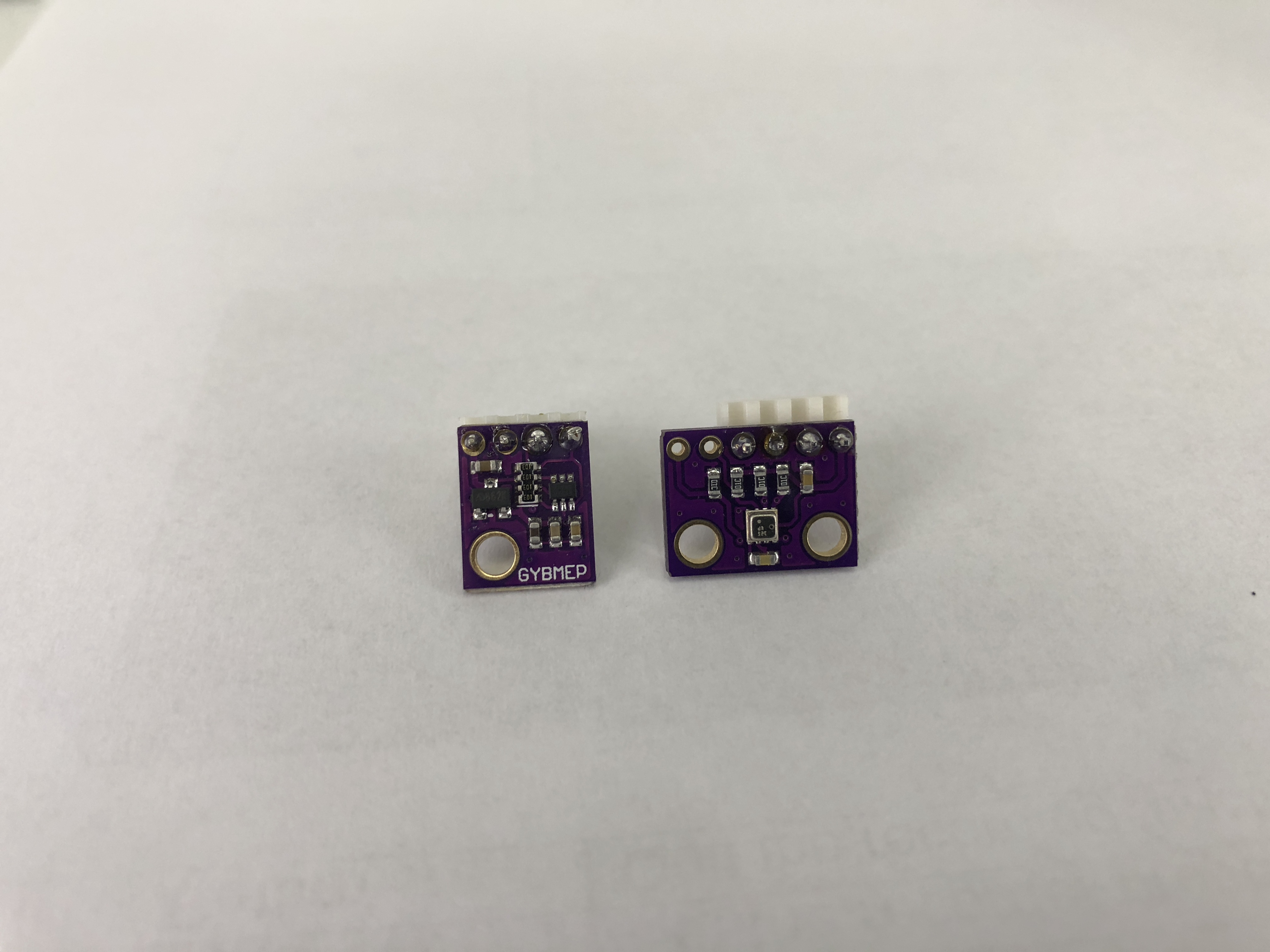
I’m aware of two different BME280 breakouts from China, a 6-pin one and a 4-pin one.
The 6-pin breakout only consist of a few parts, the BME280 sensor, some capacitors and resistors.
The 4-pin breakout consists of a few parts more, the BME280 sensor, some capacitors and resistors, a voltage regulator and a to me unknown chip.
Low power projects are often run from battery, there the amount of power over time is limited. Here the standby/sleep current is the most important one, as the sensor is most of the time doing nothing.
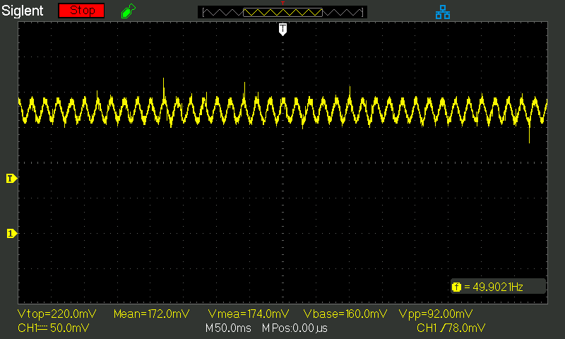
The sensor was put into ‘forced mode’ for all measurements in this post and was powered from a 3.3V source. For the measurements a Siglent SDS 1102CML+ was used combined with an uCurrent GOLD.
Stock 4-pin breakout: 7.66uA
Stock 6-pin breakout: 0.173uA
So you can clearly see, that the 6-pin breakout is better suited for low power applications as it uses 44 times less power, but you have to take care to supply the correct voltage, according to the datasheet:
‘Supply voltage VDD main supply voltage range: 1.71 V to 3.6 V’
But what happens if we do remove the voltage regulator on the 4-pin breakout?
4-pin breakout without regulator: 0.179uA
If the regulator is removed, the result is nearly the same as with the 6-pin breakout.
So you can either use the 6-Pin version or the 4-Pin version and remove the regulator and solder in a piece of wire.

Hi,thanks for the interesting article.
I have used the 6-pin version with a 3.3V ESP32 microcontroller a lot during last year and I’m happy with it.
But recently I found that 4-pin version (ordered a pack but not yet received). The 4-pin version is interesting because it has a much smaller form factor and so it fits in smaller enclosures.
What is the simplest way to disable/remove the VR on the 4-pin version? Is it the chip with 3 pins or another one? I assume I have to un-solder it but how do I then wire up the pads so the board keeps working?
Hello Adam
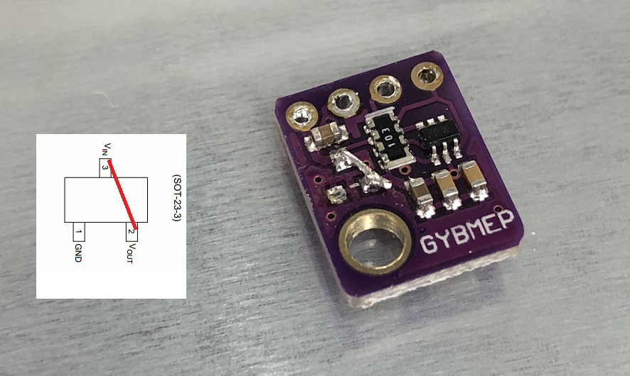
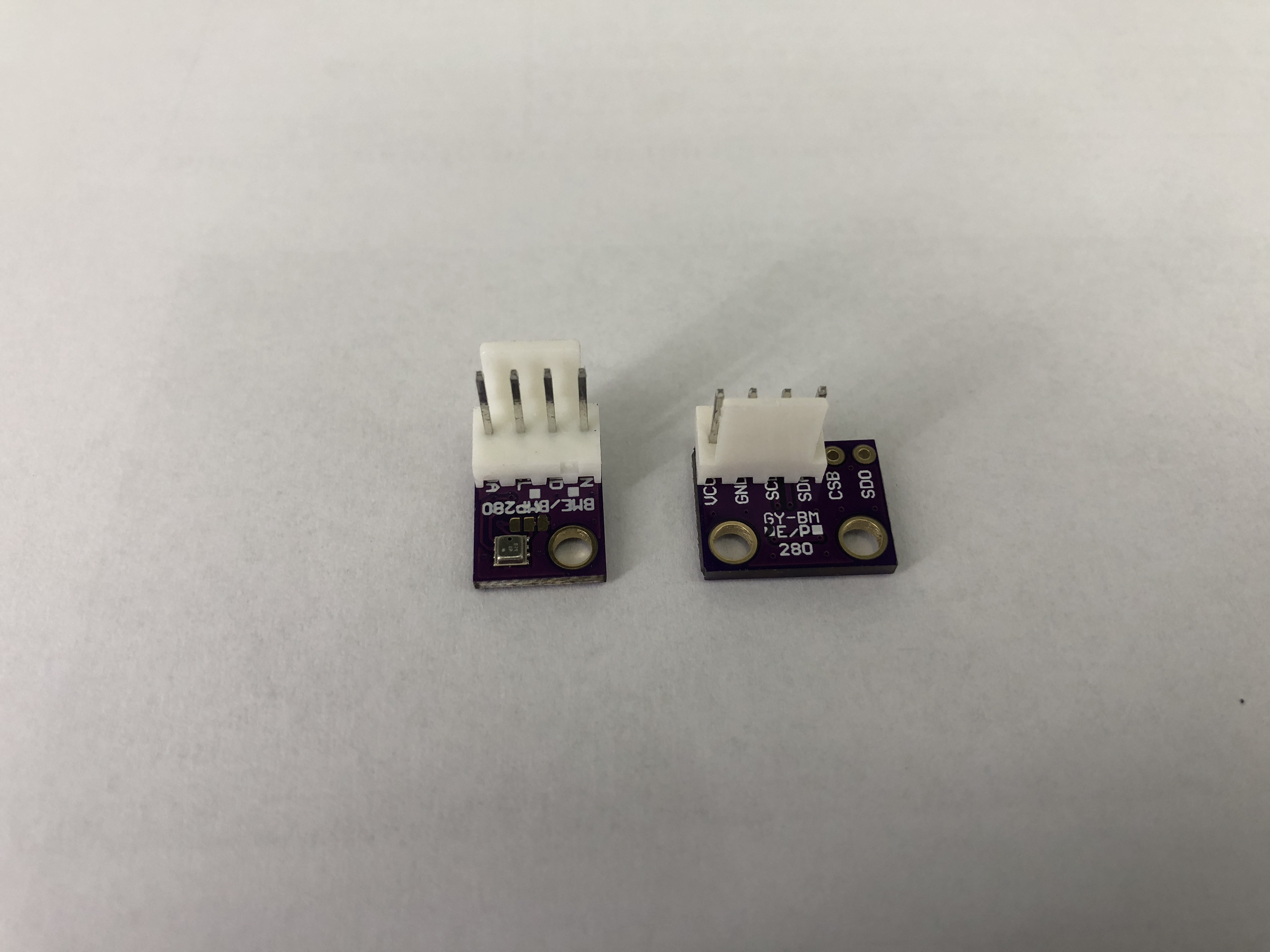
The LDO on those boards is normally a SOT-23-3, so it is the 3-Pin chip on the breakout.
On this breakouts, the left pad is normally GND, I would always recommend to check this with a multimeter (continuity test between the pad and the 2.54mm GND pin).
So the top pad and the right pad have to be bridged in this case.
Cool, thanks so much for taking the extra work and show a picture! Really appreciated!