AEMLION solar harvesting PCB tested

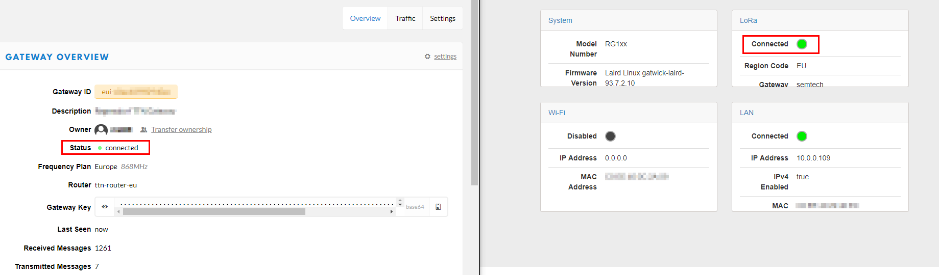
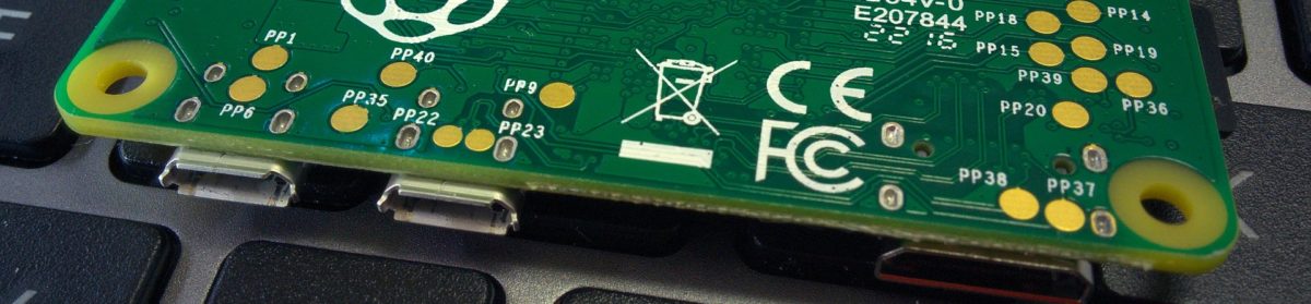
Recently I found a very interesting PCB on Tindie holding an AEM10941 Solar Harvesting IC from E-peas, thanks to Jasper Sikken for this nice board!
This chip is made to harvest energy from solar panels, even if their output is very low, as we will see later in this post.
As a nice addition, the AEM10941 does also provide two regulated outputs, on the AEMLION PCBs they are broken out, the low voltage LDO delivers 1.8V and the high voltage LDO is configured for 3.3V. This is a perfect fit for many DIY projects.

Energy harvesting

I tested three different solar panels with the board. All current measurements were made using an µCurrent GOLD Precision Current Adapter and a METRA Hit 25s multimeter. For light measurement, I used an UNI-T UT383 lux meter.
Please note that all used solar panels are cheap ones from Aliexpress and may not be within specification. With this test I simply want to show the differences in what we can get from such panels in different light conditions. Also you will see, that this PCB is really able to charge your battery even if there is only minimal light available.

Solar Paneloutdoor 95K luxoutdoor 9650 luxindoor 650 lux
2x 1V 80MA 30x25mm34ma3ma135ua
3V 120MA 52x52mm40ma6ma246ua
4V 150MA 60*80mm114ma10ma438ua

As you can see, in outdoor full sunlight (95K lux) you will get about 10x more energy out of the panels than outdoor when cloudy (9650 lux).
Indoors (650 lux) on a sunny day it is even less, it is about 150-250x less than outdoors in full sunlight.
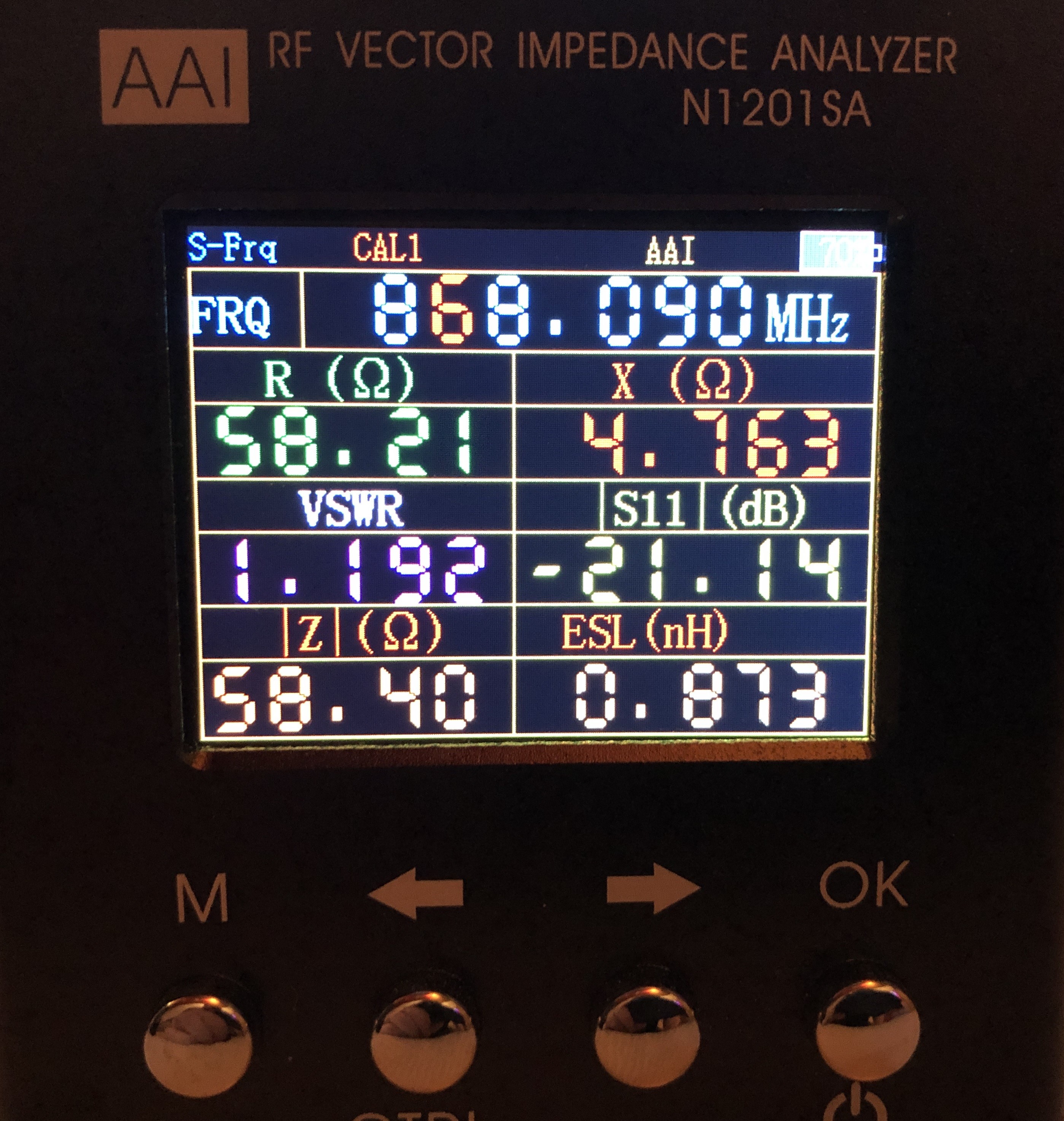
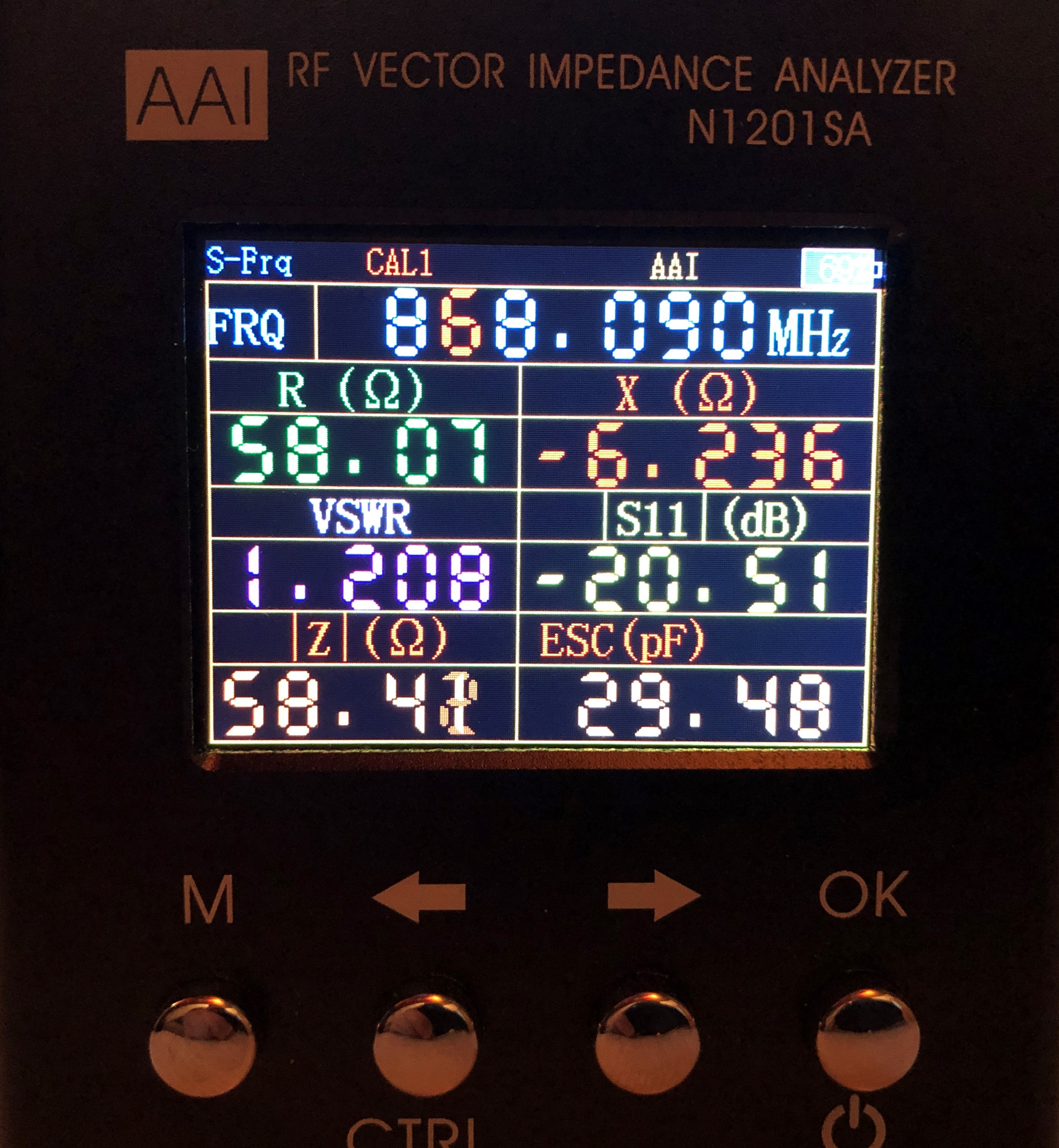
3.3V LDO output

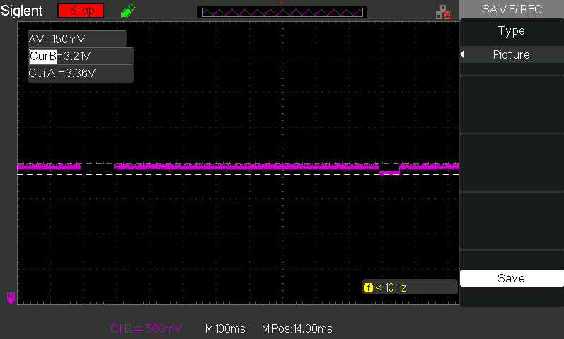
The HV LDO output is configured for 3.3V and provides up to 80 ma current with 300 mv drop-out.
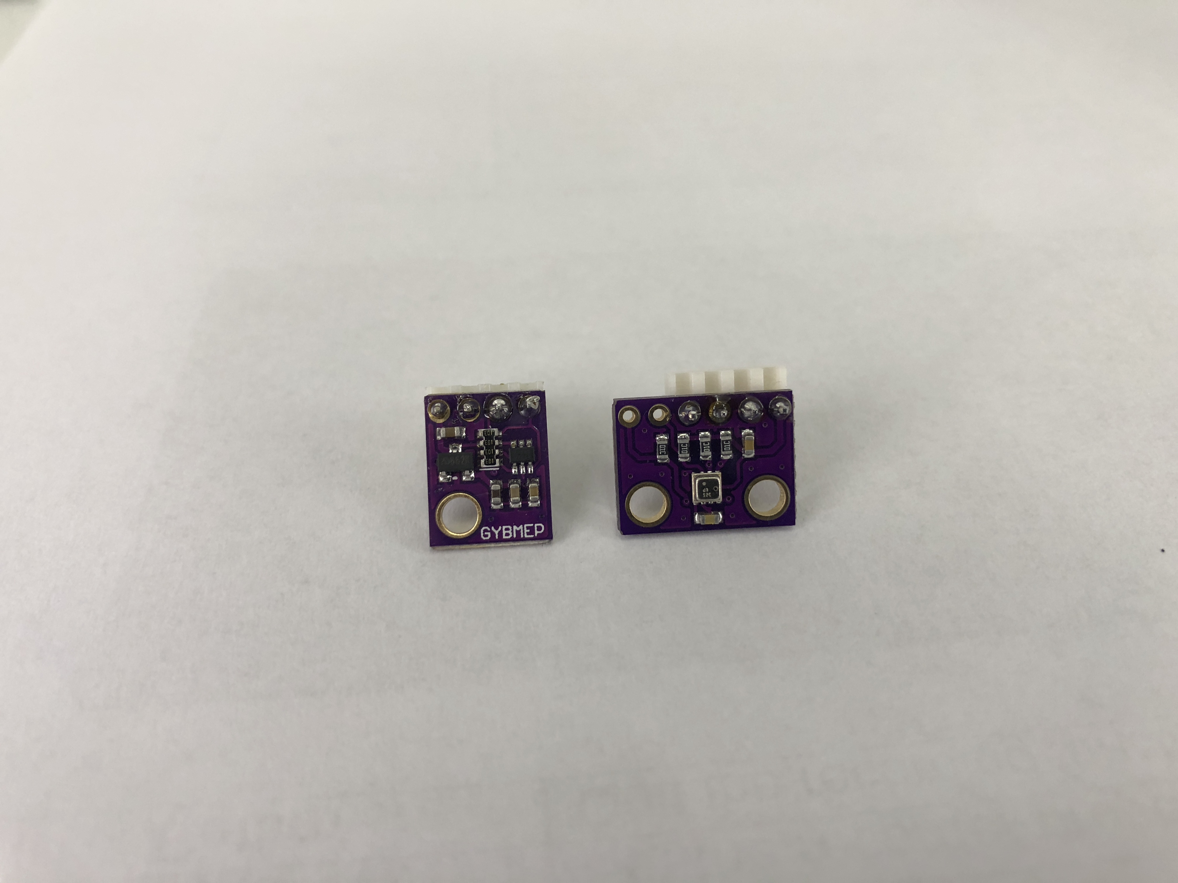
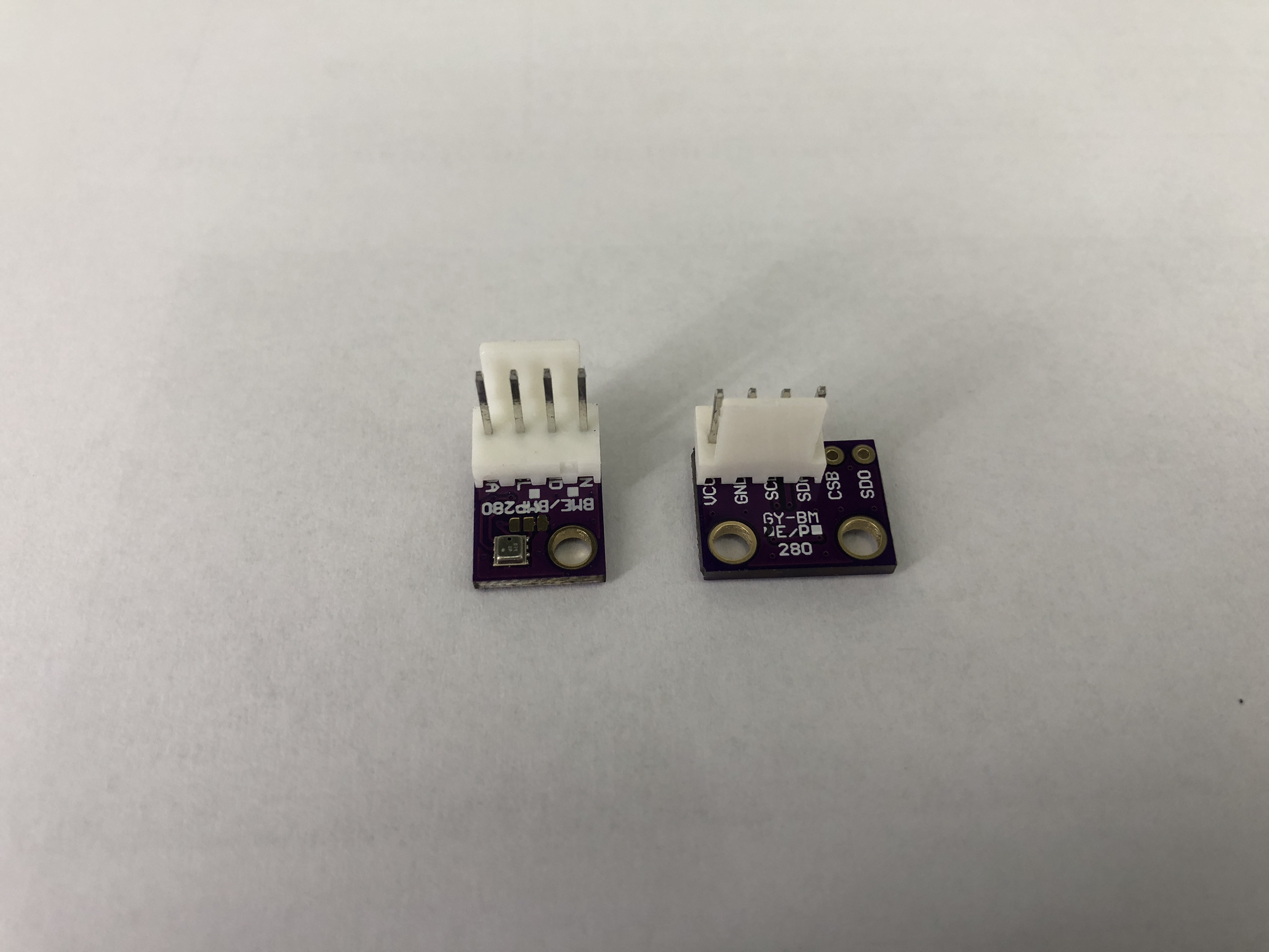
I tried to power an arduino mini pro which is configured to run on 3.3V at 8MHz. And because most of my projects are using some kind of radio communication, I added an lora RFM95 board. Of course, there has also to be some data to send over air, for that I added a BMP280 and a SI7021.
So summarized, I do power an Arduino mini pro, a RFM95 module, a BMP280 and a SI7021 from the 3.3V LDO output.
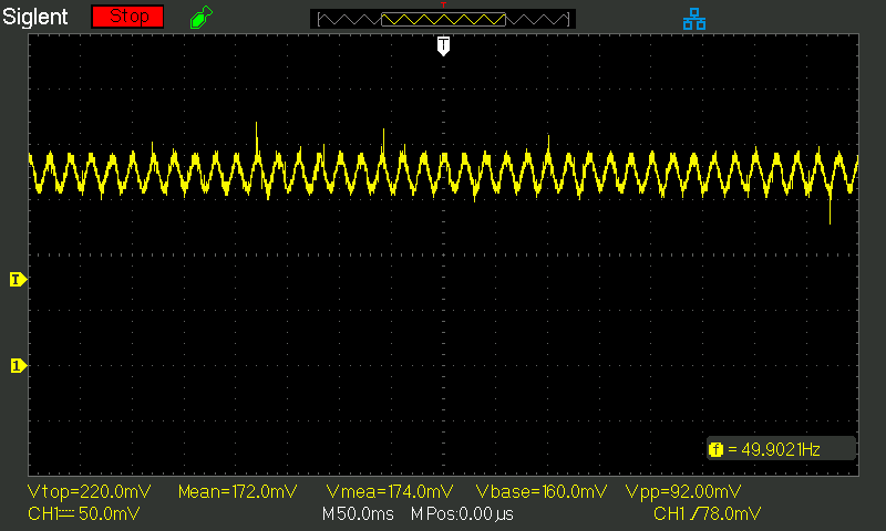
Does it work? Yes, it does! The peak current used is about 135ma, during this peak, the voltage from the LDO drops from 3.36V to about 3.21V. This is no issue as it seems, one of my sensors already sent about 10’000 measurements in this setup without any issues.
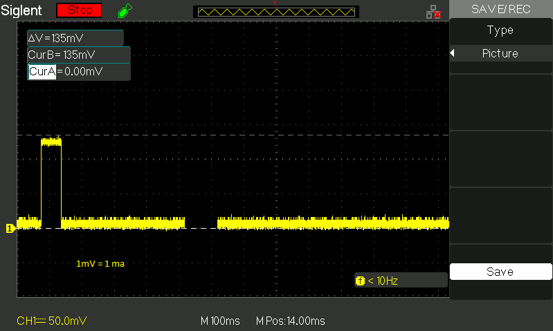
868MHz LoRa antenna from Aliexpress

Many 868MHz antennas from Aliexpress are not really designed for 868MHz but sold as such.
Therefore I would like to share two antennas with you, which are designed for 868MHz.

‘Big’ 868MHz antenna from Aliexpress
VSWR 1.19 at 868MHz, tested with N1201SA.

Small 868MHz antenna from Aliexpress
VSWR 1.20 at 868MHz, tested with N1201SA.


Bosch BME280 in low power projects

Many makers are using breakout boards for their projects, they are easy to use, as additional required components are already included on them, like pullup resistors and capacitors.

But, sometimes there are also components soldered on those breakouts which are not required for a project.

I’m aware of two different BME280 breakouts from China, a 6-pin one and a 4-pin one.
The 6-pin breakout only consist of a few parts, the BME280 sensor, some capacitors and resistors.
The 4-pin breakout consists of a few parts more, the BME280 sensor, some capacitors and resistors, a voltage regulator and a to me unknown chip.

Low power projects are often run from battery, there the amount of power over time is limited. Here the standby/sleep current is the most important one, as the sensor is most of the time doing nothing.

The sensor was put into ‘forced mode’ for all measurements in this post and was powered from a 3.3V source. For the measurements a Siglent SDS 1102CML+ was used combined with an uCurrent GOLD.

Stock 4-pin breakout: 7.66uA
Stock 6-pin breakout: 0.173uA

So you can clearly see, that the 6-pin breakout is better suited for low power applications as it uses 44 times less power, but you have to take care to supply the correct voltage, according to the datasheet:
‘Supply voltage VDD main supply voltage range: 1.71 V to 3.6 V’

But what happens if we do remove the voltage regulator on the 4-pin breakout?

4-pin breakout without regulator: 0.179uA

If the regulator is removed, the result is nearly the same as with the 6-pin breakout.
So you can either use the 6-Pin version or the 4-Pin version and remove the regulator and solder in a piece of wire.


Ultimaker PLA spool empty weight

Sometime it’s good to how much material is left on a spool. The Ultimaker spools does have a integrated NFC chip, which counts, how much material is left on the spool. Neverthless, sometimes it is good to know the empty spool weight.

Empty weight of an Ultimaker PLA spool: 230 gram

It is possible that this post will be updated in the near future with other empty spool weights.


Laird RG186 LoRa Gateway up and running within minutes

Interested to help to expand the coverage of thethingsnetwork.org project, short TTN? There are many gateway you can use, for example you can build your own TTN gateway using a RPI and a IC880a or RAK831 concentrator board.

Both solutions are priced at about CHF 150-200, depending on where you order the hardware, what kind of RPI you’re using and if you have to pay import duties or not.

But of course, you need some time to get up and running. Wiring, software and so on. Check out the TTN-ZH github page for a smooth start.

If you don’t have the time, you can buy a commercial product, the Laird RG186 gateway.

Included accessoires:

  • One 868 MHz antenna
  • Two 2.4 /5 GHz antennas
  • External DC Power Adapter
  • Ethernet cable

After you got it, simply unpackage it and plug in power and a network cable (it also has WiFi built in, but haven’t used it). Open your browser and connect to the DHCP IP address it got and log in to the device.

Default login credentials:
Username: sentrius
Password: RG1xx

Go to the ‘LoRa’ tab, and select a preset for The Things Network.

If you use ‘The Things Network Legacy EU’ you can simply apply the preset and copy the EUI displayed on the left side. Then go to https://console.thethingsnetwork.org/gateways and register the gateway. Please note to activate the checkbox ‘I’m using the legacy packet forwarder’ when registering the gateway.

If you use ‘The Things Network EU’ it is best, to go first to https://console.thethingsnetwork.org/gateways and register a new gateway, as the gateway ID can be choosen by you! After creating the gateway, copy the ‘Gateway Key’ and go the the RG186 webinterface. Apply in the ‘LoRa’ tab the preset ‘The Things Network EU’ and go then to the subtab ‘Forwarder’. Enter your ‘Gateway ID’ and the ‘Gateway Key’.

In both cases the gateway should now show up as ‘connected’, once on the RG186 dashboard and also in the TTN console.

For more detailed set-up instructions and technical specifications, please check out the official Laird RG1xx product page.